Fs ia6b wiring diagram information
Home » Trend » Fs ia6b wiring diagram information
Your Fs ia6b wiring diagram images are ready in this website. Fs ia6b wiring diagram are a topic that is being searched for and liked by netizens today. You can Get the Fs ia6b wiring diagram files here. Download all free vectors.
If you’re searching for fs ia6b wiring diagram pictures information linked to the fs ia6b wiring diagram keyword, you have visit the ideal blog. Our website frequently gives you suggestions for seeing the highest quality video and image content, please kindly hunt and find more informative video content and graphics that match your interests.
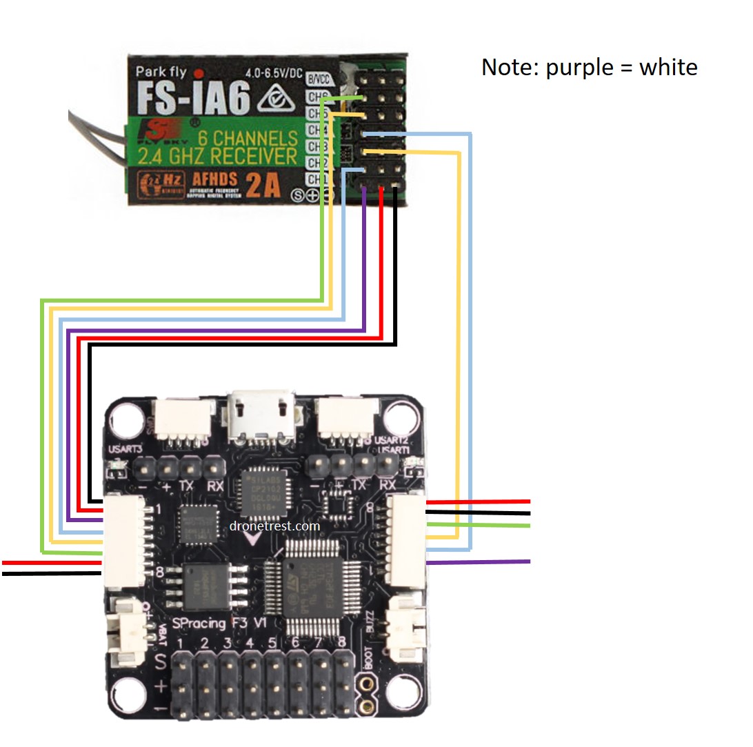
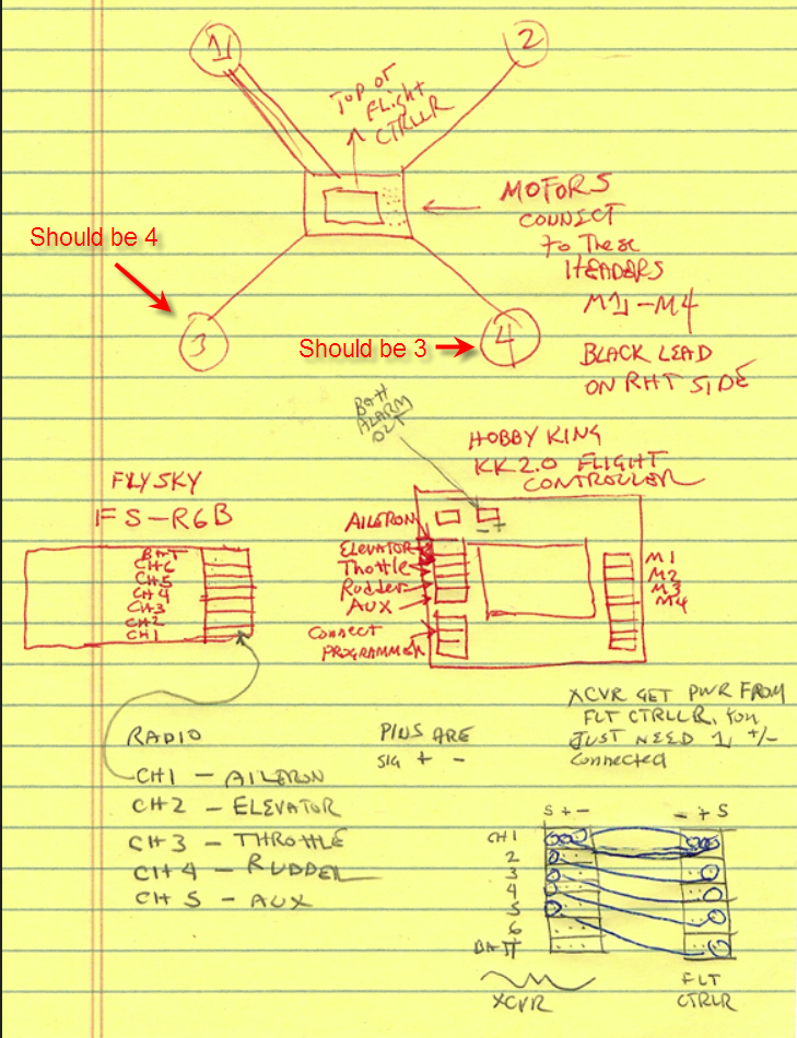
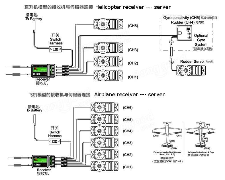
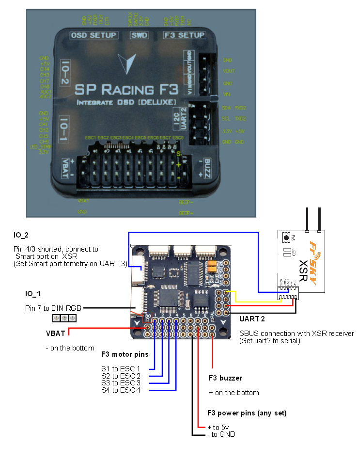
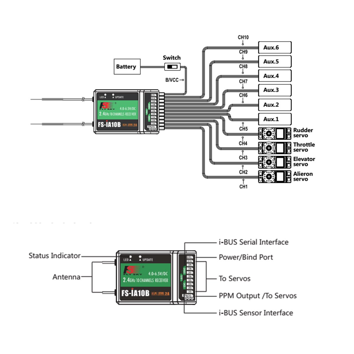
Fs Ia6b Wiring Diagram. So including power, you will need at least 6 wires connected to the receiver. A wiring diagram is a streamlined standard photographic depiction of an electric circuit. Dec 22, 2015 — flysky rc model technology co., ltd. Superwinch atv 2000 wiring diagram wiring diagram is a simplified up to standard pictorial representation of an electrical circuit it shows the components of the circuit as simplified shapes and the aptitude and signal friends together with the devices.
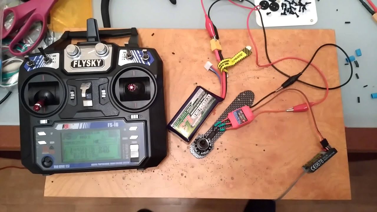 Fsia6 Wiring Diagram From wiringall.com
Direct tv hd antenna wiring diagram direct get free free tv channels receiver antenna the fs i6s transmitter and fs ia6b receiver constitute a 10 channel 2 4ghz afhds 2a digital proportional. Ppm modes is that you don t need to keep track of all of your cables typically one per channel. I have no idea why manufacturer keeps ppm support data so well hidden. • for best signal quality, make sure that the antenna is at about a.digital proportional radio control system. Ibus telemetry is not currently supported by betaflight but it is forthcoming. Come explore, share, and make your next project with us!instructables is a community for people who like to make things.
There you can find the wiring diagram that i ve personally tested and as soon as i get.
Insert the standard bind cable into the power supply channel. Dec 22, 2015 — flysky rc model technology co., ltd. Shielded interface cables when connecting to computer or peripheral devices. Ppm modes is that you don t need to keep track of all of your cables typically one per channel. 2.1 system features the afhds 2a (automatic frequency hopping digital system second generation) developed and patented by flysky is specially developed for all radio control models. Come explore, share, and make your next project with us!instructables is a community for people who like to make things.
 Source: youtube.com
Open the main menu, and select rx setup function in the second page, then touch bind with a receiver to enter bind mode. Insert the standard bind cable into the power supply channel. See more of my drones & r/c videos here again, the antennae are not replaceable. Visit howstuffworks to check out this brake light wiring diagram. Button on the throttle to get that value or consult your flysky radio�s manual.
 Source: webanalytik.info
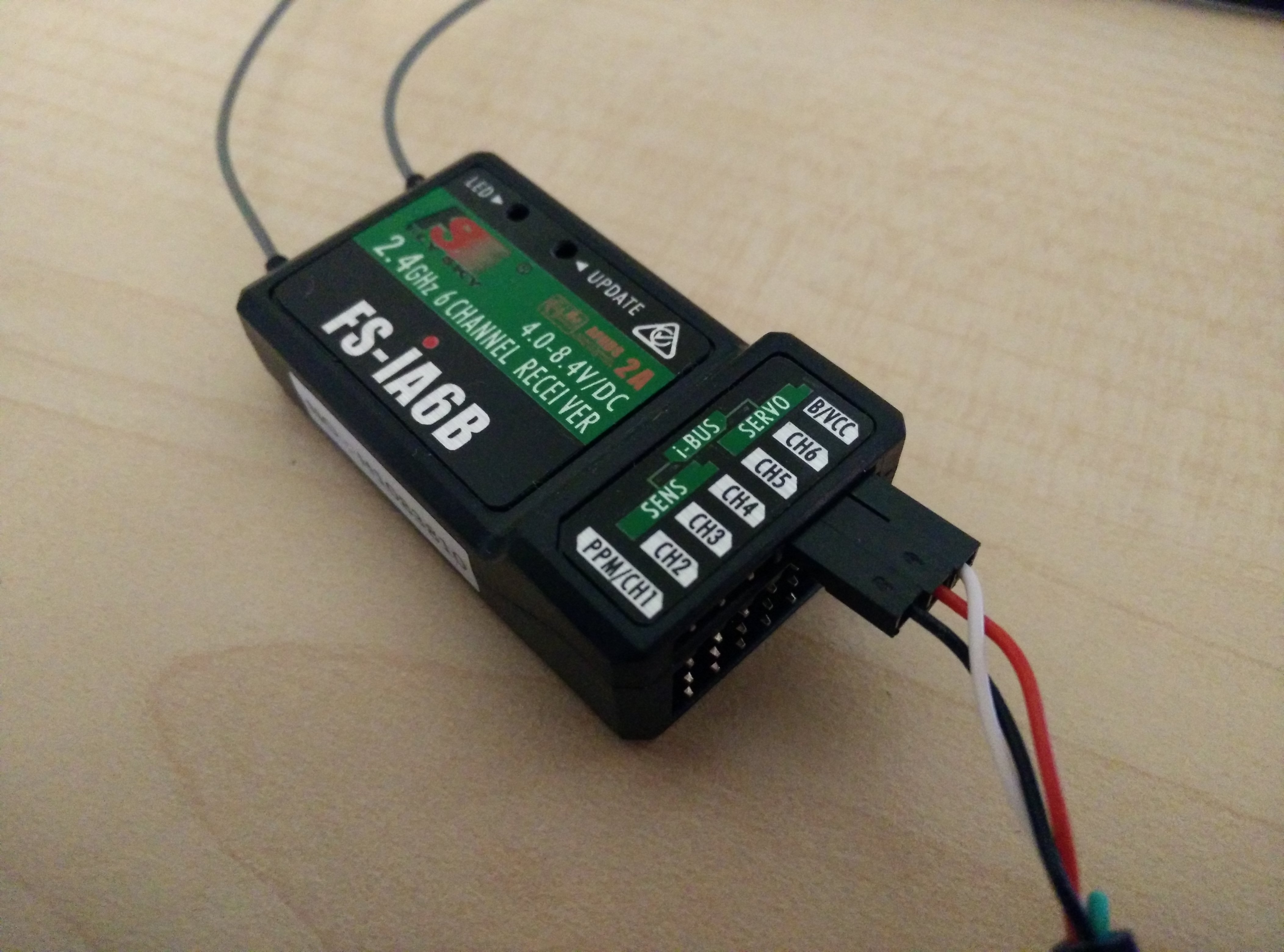
A wiring diagram is a streamlined standard photographic depiction of an electric circuit. Luckily, there are some places that may have. Bind before you depin i forgot to and it�s a lot harder to do after the fact. The “servo” slot is the ibus output from the receiver, into which you will plug the servo wire coming out of your flight. Elevator on naza.nov 12, · dji phantom 3 standard wiring diagram dji phantom 3 camera wiring diagram rc groups discussion dji phantom 3 camera wiring diagram multirotor drone electronics.
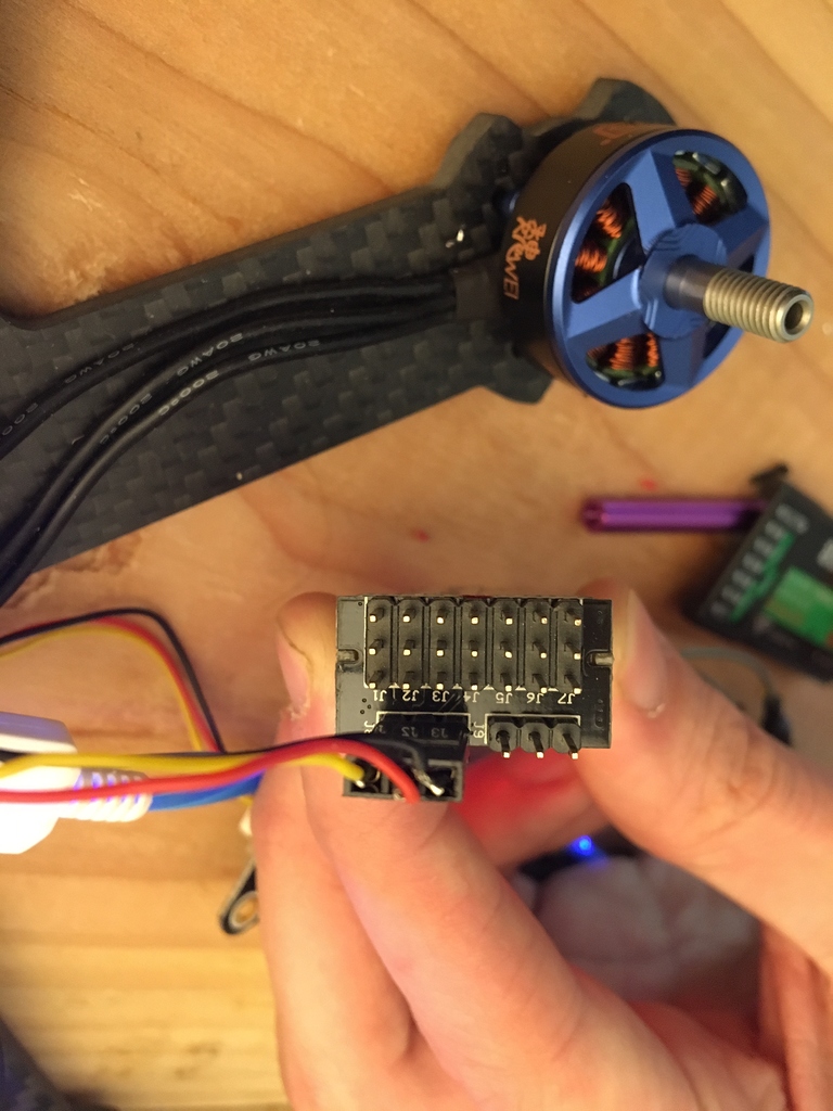 Source: dronetrest.com
• for best signal quality, make sure that the antenna is at about a.digital proportional radio control system. How can i enable ppm on i6 radio system? Direct tv hd antenna wiring diagram direct get free free tv channels receiver antenna the fs i6s transmitter and fs ia6b receiver constitute a 10 channel 2 4ghz afhds 2a digital proportional. Luckily, there are some places that may have. Direct tv hd antenna wiring diagram direct get free free tv channels receiver antenna the fs i6s transmitter and fs ia6b receiver constitute a 10 channel 2 4ghz afhds 2a.
 Source: schematron.org
Direct tv hd antenna wiring diagram direct get free free tv channels receiver antenna the fs i6s transmitter and fs ia6b receiver constitute a 10 channel 2 4ghz afhds 2a digital proportional. Page new product kingkong 90gt 90mm brushless fpv racer micro multirotor drones. Ppm modes is that you don t need to keep track of all of your cables typically one per channel. For a boombox schematic in particula. Getting fs a8s receiver working with omnibus f4 v6 fc help dronetrest from www.dronetrest.com such a major improvement over stock.
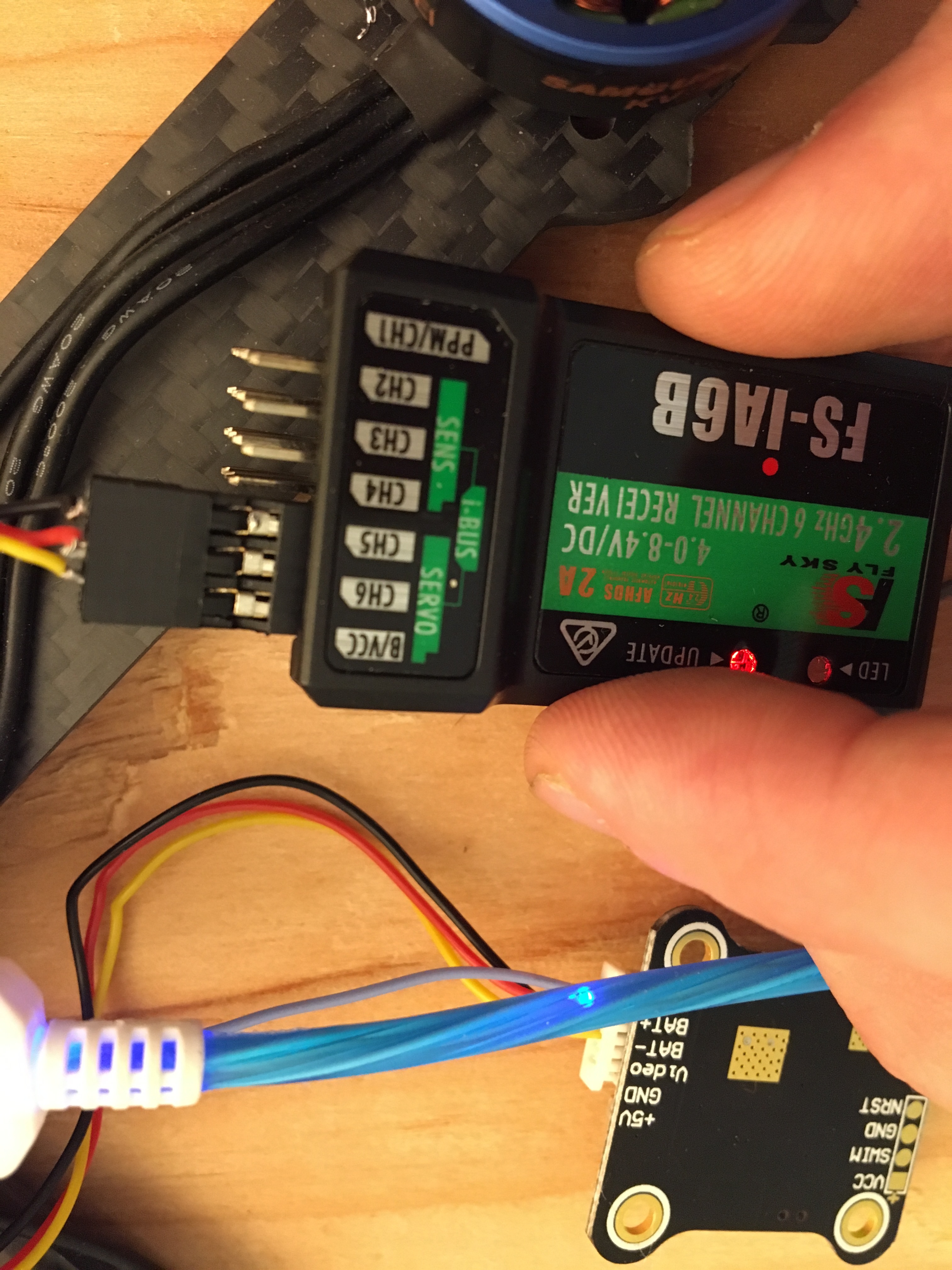 Source: dronetrest.com
Wiring wiring diagram» fs ia6 receiver wire diagram. The switches can be assigned to various functions for quick access. See more of my drones & r/c videos here again, the antennae are not replaceable. Wiring wiring diagram» fs ia6 receiver wire diagram. So including power, you will need at least 6 wires connected to the receiver.
 Source: wiringall.com
For a boombox schematic in particula. Wiring wiring diagram» fs ia6 receiver wire diagram. See more of my drones & r/c videos here again, the antennae are not replaceable. Check the flight controller manual to see which of those breakout harnesses with the. 1 trick that i 2 to print a similar wiring diagram off twice.
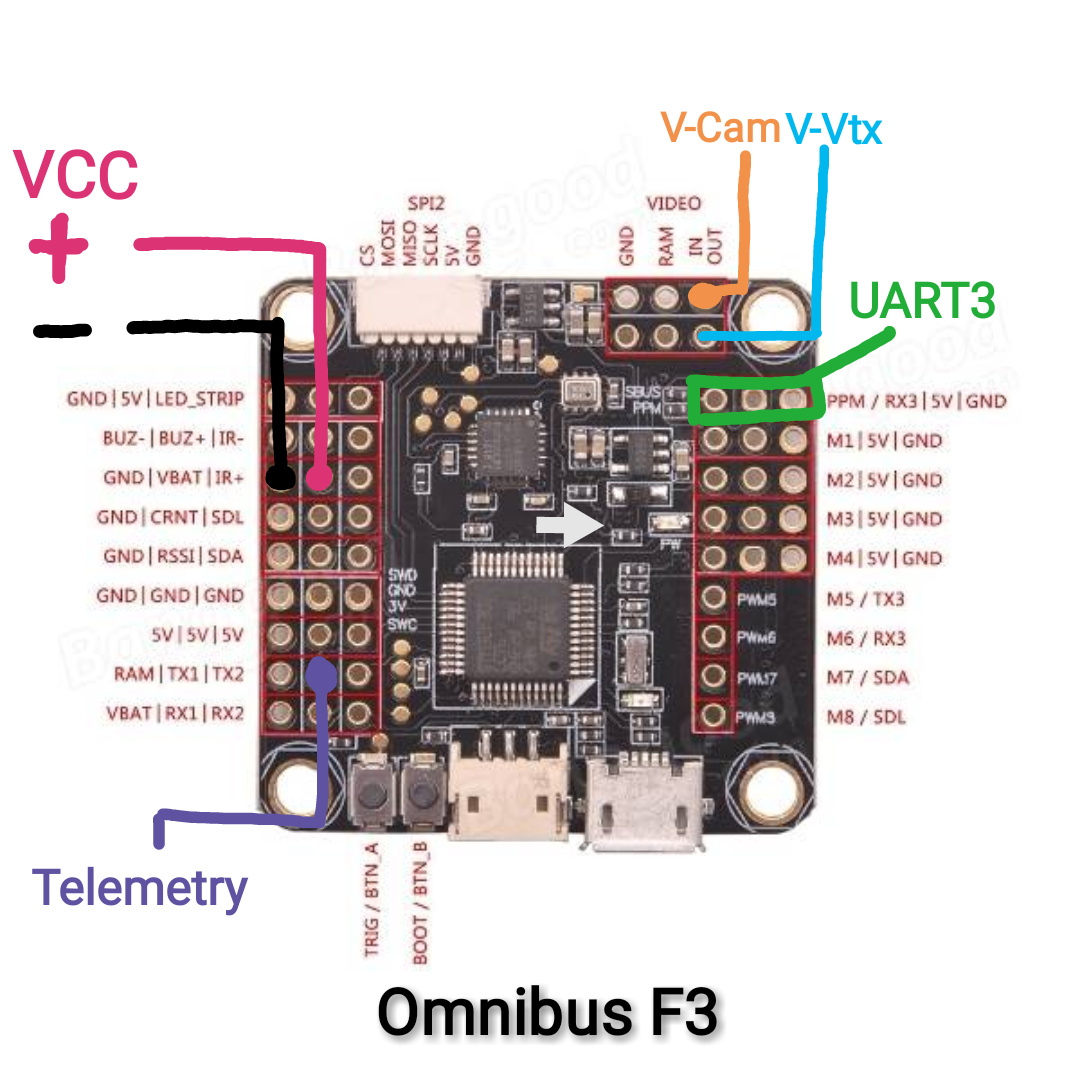 Source: schematron.org
• for best signal quality, make sure that the antenna is at about a.digital proportional radio control system. The fs i6s transmitter and fs ia6b receiver constitute a 10 channel. 1 trick that i 2 to print a similar wiring diagram off twice. Wiring wiring diagram» fs ia6 receiver wire diagram. Luckily, there are some places that may have.
 Source: forum.wearefpv.fr
Come explore, share, and make your next project with us!instructables is a community for people who like to make things. Bind before you depin i forgot to and it�s a lot harder to do after the fact. But support for ppm (cppm) standard is somehow not clear. A wiring diagram is a streamlined standard photographic depiction of an electric circuit. For a boombox schematic in particula.
 Source: reddit.com
See more of my drones & r/c videos here again, the antennae are not replaceable. Shielded interface cables when connecting to computer or peripheral devices). How can i enable ppm on i6 radio system? Insert the standard bind cable into the power supply channel. The fs i6s transmitter and fs ia6b receiver constitute a 10 channel.
 Source: notsyncing.net
2.1 system features the afhds 2a (automatic frequency hopping digital system second generation) developed and patented by flysky is specially developed for all radio control models. Ibus telemetry is not currently supported by betaflight but it is forthcoming. Superwinch atv 2000 wiring diagram wiring diagram is a simplified up to standard pictorial representation of an electrical circuit it shows the components of the circuit as simplified shapes and the aptitude and signal friends together with the devices. But support for ppm (cppm) standard is somehow not clear. First you will have to take it out of it�s case (obviously) then follow the vid.
 Source: schematron.org
Connect the 6vdc power connector to any channel from ch1 to ch 6 with correct polarity to enter bind mode, the receiver. First you will have to take it out of it�s case (obviously) then follow the vid. How can i enable ppm on i6 radio system? 1 trick that i 2 to print a similar wiring diagram off twice. Shielded interface cables when connecting to computer or peripheral devices).
 Source: wiringall.com
1 trick that i 2 to print a similar wiring diagram off twice. Direct tv hd antenna wiring diagram direct get free free tv channels receiver antenna the fs i6s transmitter and fs ia6b receiver constitute a 10 channel 2 4ghz afhds 2a. Page new product kingkong 90gt 90mm brushless fpv racer micro multirotor drones. Shielded interface cables when connecting to computer or peripheral devices). Elevator on naza.nov 12, · dji phantom 3 standard wiring diagram dji phantom 3 camera wiring diagram rc groups discussion dji phantom 3 camera wiring diagram multirotor drone electronics.
 Source: lelong.com.my
• for best signal quality, make sure that the antenna is at about a.digital proportional radio control system. So including power, you will need at least 6 wires connected to the receiver. But support for ppm (cppm) standard is somehow not clear. Wiring wiring diagram» fs ia6 receiver wire diagram. There you can find the wiring diagram that i ve personally tested and as soon as i get.
 Source: wiringall.com
Come explore, share, and make your next project with us!instructables is a community for people who like to make things. So including power, you will need at least 6 wires connected to the receiver. How can i enable ppm on i6 radio system? Visit howstuffworks to check out this brake light wiring diagram. • for best signal quality, make sure that the antenna is at about a.digital proportional radio control system.
 Source: schematron.org
View fs ia6b wiring diagram png. There you can find the wiring diagram that i ve personally tested and as soon as i get. Ppm modes is that you don t need to keep track of all of your cables typically one per channel. Aclk sa l ai dchcsewjh77tjojr0ahx0j2gjhbugdfsyababggj3zg sig aod64 19zpywv0tn6odskgh1bl66og24bg adurl ctype 5 : So including power, you will need at least 6 wires connected to the receiver.
 Source: youtube.com
The fs i6s transmitter and fs ia6b receiver constitute a 10 channel. A wiring diagram is a streamlined standard photographic depiction of an electric circuit. Visit howstuffworks to check out this brake light wiring diagram. When you make use of your finger or even stick to the circuit together with your eyes, it may be easy to mistrace the circuit. Elevator on naza.nov 12, · dji phantom 3 standard wiring diagram dji phantom 3 camera wiring diagram rc groups discussion dji phantom 3 camera wiring diagram multirotor drone electronics.
 Source: wiringall.com
1 trick that i 2 to print a similar wiring diagram off twice. First you will have to take it out of it�s case (obviously) then follow the vid. Wiring wiring diagram» fs ia6 receiver wire diagram. Open the main menu, and select rx setup function in the second page, then touch bind with a receiver to enter bind mode. Aclk sa l ai dchcsewjh77tjojr0ahx0j2gjhbugdfsyababggj3zg sig aod64 19zpywv0tn6odskgh1bl66og24bg adurl ctype 5 :
 Source: wiringall.com
For a boombox schematic in particula. Check the flight controller manual to see which of those breakout harnesses with the. The “servo” slot is the ibus output from the receiver, into which you will plug the servo wire coming out of your flight. How can i enable ppm on i6 radio system? Come explore, share, and make your next project with us!instructables is a community for people who like to make things.
This site is an open community for users to do sharing their favorite wallpapers on the internet, all images or pictures in this website are for personal wallpaper use only, it is stricly prohibited to use this wallpaper for commercial purposes, if you are the author and find this image is shared without your permission, please kindly raise a DMCA report to Us.
If you find this site serviceableness, please support us by sharing this posts to your own social media accounts like Facebook, Instagram and so on or you can also bookmark this blog page with the title fs ia6b wiring diagram by using Ctrl + D for devices a laptop with a Windows operating system or Command + D for laptops with an Apple operating system. If you use a smartphone, you can also use the drawer menu of the browser you are using. Whether it’s a Windows, Mac, iOS or Android operating system, you will still be able to bookmark this website.
Category
Related By Category
- Predator 670 engine wiring diagram Idea
- Frsky x8r wiring diagram information
- Pioneer ts wx130da wiring diagram Idea
- Johnson 50 hp wiring diagram Idea
- Kohler voltage regulator wiring diagram Idea
- Johnson 50 hp outboard wiring diagram information
- Kti hydraulic remote wiring diagram Idea
- Pyle plpw12d wiring diagram information
- Tx9600ts wiring diagram information
- Lifan 50cc wiring diagram information