Freezer defrost timer wiring diagram Idea
Home » Trending » Freezer defrost timer wiring diagram Idea
Your Freezer defrost timer wiring diagram images are ready. Freezer defrost timer wiring diagram are a topic that is being searched for and liked by netizens now. You can Find and Download the Freezer defrost timer wiring diagram files here. Download all free photos and vectors.
If you’re looking for freezer defrost timer wiring diagram images information related to the freezer defrost timer wiring diagram keyword, you have come to the ideal site. Our website always gives you hints for viewing the maximum quality video and picture content, please kindly search and find more enlightening video articles and graphics that fit your interests.
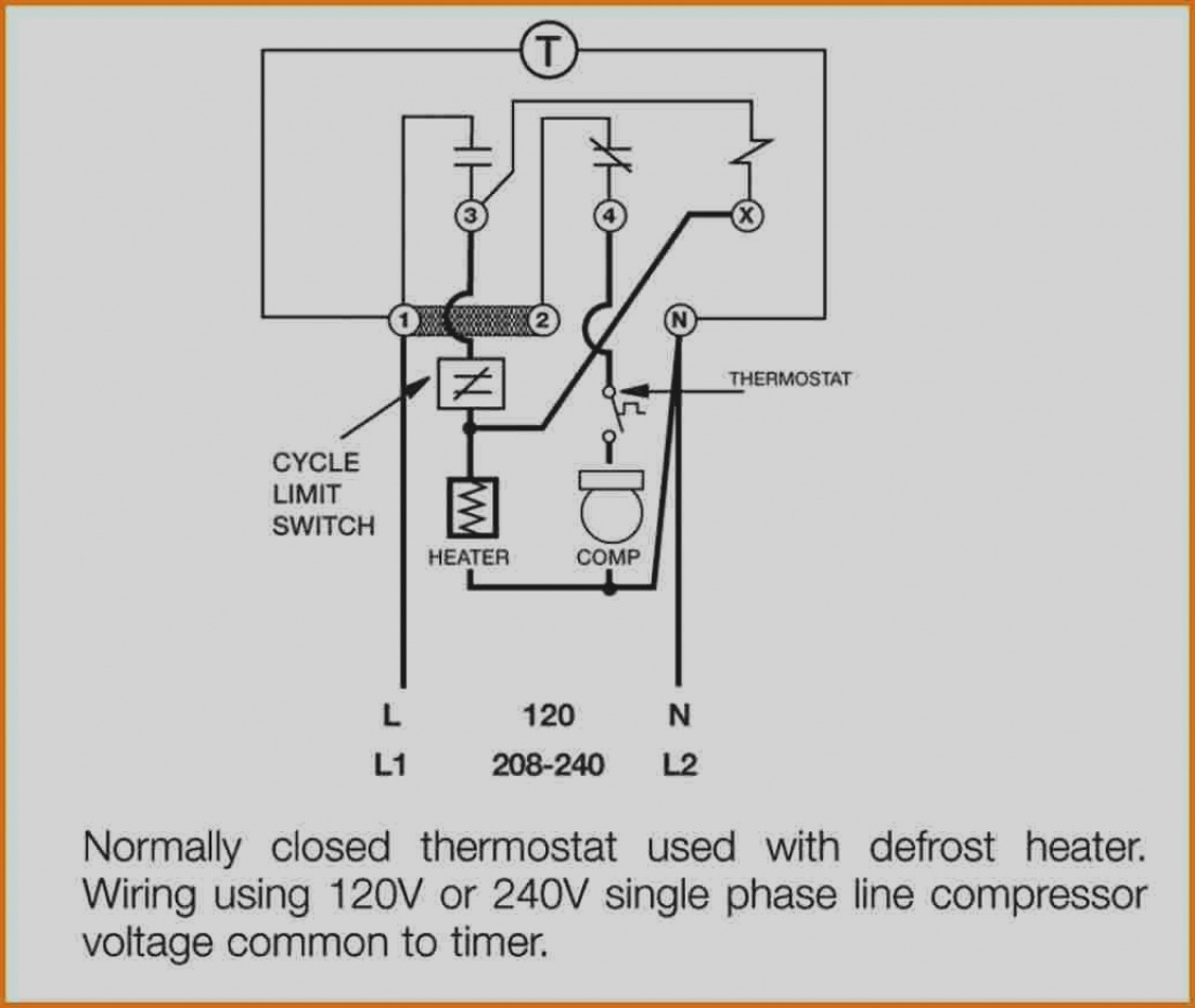
Freezer Defrost Timer Wiring Diagram. Adjust between 120 vac and 240 vac operation. The replacement timer (pn 482493) appears to be a universal replacement for several models. The paragon defrost and the tork electric timers. Set the correct time of day on the defrost timer.
 Freezer Defrost Timer Wiring Diagram Wiring Diagram And From tops-stars.com
Louvered grill, wiring diagram is positioned on the. Freezer defrost timer wiring diagram. Walk in freezer defrost timer wiring diagram. If your meter reads the proper voltage, then the timer board is good and is supplying power to the gear motor relay or circuit. The most common form of defrosting a freezer�s unit cooler is done by control for the evaporator is wired to terminal “x” on the defrost timer. A wiring diagram is a simplified standard pictorial depiction of an electric circuit.
The defrost timer now begins steadily advancing again, and soon switches the compressor back on, and we’re back where we started, in the normal mode of operation.
The new replacement timer, part# 482493 is a universal whirlpool timer. Piece p id 14497442548 tmde706sc china and made in w10822278 part fast shipping partselect troubleshooting puzzle reach freezer that not keeping product frozen 2021 08 12 achr news universal timers 9145. This type of wiring diagram has branch runs all shown as parallel circuits going from the left line l1 to the neutral line n. Heatcraft wiring diagram walk in freezer defrost timer wiring diagram wiring credit. Testing a fridge /freezer / refrigerator defrost timer to the timer can only be connected one way, so it�s not important to draw a wiring schematic for this job. Grasslin defrost timer (freezer units only).
 Source: dentistmitcham.com
It reveals the components of the circuit as streamlined shapes as well as the power and signal connections in between the devices. 13 true will not warranty any refrigerator that has been. It reveals the components of the circuit as streamlined shapes as well as the power and signal connections in between the devices. Diagram 7 typical wiring diagram for single evaporator single phase defrost and evaporator fan contactors. 29.08.2021 · is the on timer set?
 Source: worldvisionsummerfest.com
The timer is connected into a wiring harness in the housing with a drain tube that goes into the back of the fridge. Adjust between 120 vac and 240 vac operation. Set the correct time of day on the defrost timer. Freezer defrost timer wiring diagram. To reference wiring diagram remove front louvered grill.
 Source: tops-stars.com
The defrost timer now begins steadily advancing again, and soon switches the compressor back on, and we’re back where we started, in the normal mode of operation. Walk in freezer defrost timer wiring diagram. The instruction that came with it indicate three different ways to hook it up, depending on how the freezer is wired. The orange wire goes to the thermostat and the red wire goes to the motors. Diagram 7 typical wiring diagram for single evaporator single phase defrost and evaporator fan contactors.
Source: skippingtheinbetween.blogspot.com
It starts the defrost heater�s circuit to melt ice or frost on the evaporator to block airflow. The most common form of defrosting a freezer�s unit cooler is done by using electric heaters embedded in the fin coil and controlling the heaters with a timer. Wires) n=white (neutral) x=purple (defrost termination) this info obtained from sheet included with the grasslin timer for the true freezer. If your meter reads the proper voltage, then the timer board is good and is supplying power to the gear motor relay or circuit. The defrost timer shall also incorporate a short cycle delay
 Source: wiring89.blogspot.com
Purchased a new defrost timer for model #106722541 kenmore coldspot freezers. How to test paragon defrost timer. I cant seem to find a wiring diagram on how to wire this correctly link below has wiring diagrams and wiring. I can�t find the wiring diagram for the freezer so i need do know which procedure in the instructions i need to use to. It reveals the components of the circuit as streamlined shapes as well as the power and signal connections in between the devices.
 Source: diagramweb.net
I can�t find the wiring diagram for the freezer so i need do know which procedure in the instructions i need to use to. Unique walk in freezer defrost timer wiring diagram diagram walk in freezer whirlpool refrigerator the diagram shows an evaporator which is fed by a thermostatic expansion valve with internal pressure. It reveals the components of the circuit as streamlined shapes as well as the power and signal connections in between the devices. The instructions suggest comparing it with the wiring diagram of the freezer for proper hook up. Set the correct time of day on the defrost timer.
 Source: atkinsjewelry.blogspot.com
Purchased a new defrost timer for model #106722541 kenmore coldspot freezers. Set the correct time of day on the defrost timer. Find out how to repair a refrigerator and freezer that Louvered grill, wiring diagram is positioned on the. Testing a fridge /freezer / refrigerator defrost timer to the timer can only be connected one way, so it�s not important to draw a wiring schematic for this job.
 Source: skippingtheinbetween.blogspot.com
Variety of true freezer t 49f wiring diagram. Wiring diagram for defrost timer wiring diagram line wiring diagram. Wires) n=white (neutral) x=purple (defrost termination) this info obtained from sheet included with the grasslin timer for the true freezer. Unique walk in freezer defrost timer wiring diagram diagram walk in freezer whirlpool refrigerator the diagram shows an evaporator which is fed by a thermostatic expansion valve with internal pressure. Walk in freezer defrost timer wiring diagram wiring diagram is a simplified suitable pictorial representation of an electrical circuit it shows the components of the circuit as simplified shapes and the skill and signal associates together with the devices.
 Source: tops-stars.com
Are the horizontal vane and the vertical vane installed correctly? The defrost timer now begins steadily advancing again, and soon switches the compressor back on, and we’re back where we started, in the normal mode of operation. 29.08.2021 · is the on timer set? Walk in freezer defrost timer wiring diagram. To reference wiring diagram remove front louvered grill.
 Source: worldvisionsummerfest.com
It reveals the parts of the circuit as simplified forms as well as the power and also signal connections between the tools. In this video you can learn about the defrost timer wiring diagram of a frost free refrigerator and circuit diagram step by step details about the function o. The most common form of defrosting a freezer�s unit cooler is done by using electric heaters embedded in the fin coil and controlling the heaters with a timer. The replacement timer (pn 482493) appears to be a universal replacement for several models. The most common form of defrosting a freezer�s unit cooler is done by control for the evaporator is wired to terminal “x” on the defrost timer.
 Source: tonetastic.info
Variety of true freezer t 49f wiring diagram. To reference wiring diagram remove front louvered grill. The defrost timer shall also incorporate a short cycle delay 29.08.2021 · is the on timer set? The instructions suggest comparing it with the wiring diagram of the freezer for proper hook up.
 Source: worldvisionsummerfest.com
After the timer measures an accumulated run time equal to a predetermined amount, the system will enter into the defrost cycle. Walk in freezer paragon defrost control. Are the horizontal vane and the vertical vane installed correctly? Timer only advances when the compressor is running. How to test paragon defrost timer.
 Source: schematron.org
Walk in freezer wiring diagram. A first check out a circuit layout could be complicated however if you could check out a subway map you could read schematics. Wiring diagram for defrost timer wiring diagram line wiring diagram. The defrost timer shall also incorporate a short cycle delay Grasslin defrost timer (freezer units only).
 Source: skippingtheinbetween.blogspot.com
If your meter reads the proper voltage, then the timer board is good and is supplying power to the gear motor relay or circuit. The orange wire goes to the thermostat and the red wire goes to the motors. Timer only advances when the compressor is running. The defrost timer shall also incorporate a short cycle delay Even the cumulative defrost systems fail to account for the number of times the door is opened
 Source: ricardolevinsmorales.com
Are the horizontal vane and the vertical vane installed correctly? Wiring diagram for defrost timer wiring diagram line wiring diagram. The replacement timer (pn 482493) appears to be a universal replacement for several models. In this video you can learn about the defrost timer wiring diagram of a frost free refrigerator and circuit diagram step by step details about the function o. The instructions suggest comparing it with the wiring diagram of the freezer for proper hook up.
 Source: agurlhasherownstory.blogspot.com
Wiring diagram for defrost timer wiring diagram line wiring diagram. Louvered grill, wiring diagram is positioned on the. For example , in case a module is powered up and it sends out a signal of half the voltage in addition to the technician will not know this, he would think he has a challenge, as this. Get shopping advice from experts, friends and the community! Retail store walk in coolers and freezers boiler operating control used as a thermostat universal defrost timer wiring.
 Source: hanenhuusholli.blogspot.com
Walk in freezer defrost timer wiring diagram. Purchased a new defrost timer for model #106722541 kenmore coldspot freezers. Testing a fridge /freezer / refrigerator defrost timer to the timer can only be connected one way, so it�s not important to draw a wiring schematic for this job. Grasslin defrost timer (freezer units only). In this video you can learn about the defrost timer wiring diagram of a frost free refrigerator and circuit diagram step by step details about the function o.
 Source: schematron.org
Retail store walk in coolers and freezers boiler operating control used as a thermostat universal defrost timer wiring. Get shopping advice from experts, friends and the community! Find out how to repair a refrigerator and freezer that Louvered grill, wiring diagram is positioned on the. Purchased a new defrost timer for model #106722541 kenmore coldspot freezers.
This site is an open community for users to submit their favorite wallpapers on the internet, all images or pictures in this website are for personal wallpaper use only, it is stricly prohibited to use this wallpaper for commercial purposes, if you are the author and find this image is shared without your permission, please kindly raise a DMCA report to Us.
If you find this site serviceableness, please support us by sharing this posts to your own social media accounts like Facebook, Instagram and so on or you can also bookmark this blog page with the title freezer defrost timer wiring diagram by using Ctrl + D for devices a laptop with a Windows operating system or Command + D for laptops with an Apple operating system. If you use a smartphone, you can also use the drawer menu of the browser you are using. Whether it’s a Windows, Mac, iOS or Android operating system, you will still be able to bookmark this website.
Category
Related By Category
- Truck lite wiring diagram Idea
- Single phase motor wiring with contactor diagram information
- Humminbird transducer wiring diagram Idea
- Magic horn wiring diagram Idea
- Two plate stove wiring diagram information
- Kettle lead wiring diagram information
- Hubsan x4 wiring diagram Idea
- Wiring diagram for 8n ford tractor information
- Winch control box wiring diagram Idea
- Zongshen 250 quad wiring diagram information