Franklin well pump control box wiring diagram information
Home » Trending » Franklin well pump control box wiring diagram information
Your Franklin well pump control box wiring diagram images are ready. Franklin well pump control box wiring diagram are a topic that is being searched for and liked by netizens today. You can Find and Download the Franklin well pump control box wiring diagram files here. Find and Download all free vectors.
If you’re looking for franklin well pump control box wiring diagram images information connected with to the franklin well pump control box wiring diagram keyword, you have come to the right site. Our website frequently provides you with suggestions for seeing the highest quality video and image content, please kindly search and locate more informative video content and images that match your interests.
Franklin Well Pump Control Box Wiring Diagram. Franklin well pump control box wiring diagram wiring diagram is a simplified normal pictorial representation of an electrical circuit. 3 the arp control yellow wire will be connected to control box 2. Submersible pump control box wiring diagram building circuitry diagrams reveal the approximate areas and affiliations of receptacles lights and also. Visually inspect the control panel�s wires, wire connections, relay and capacitor.
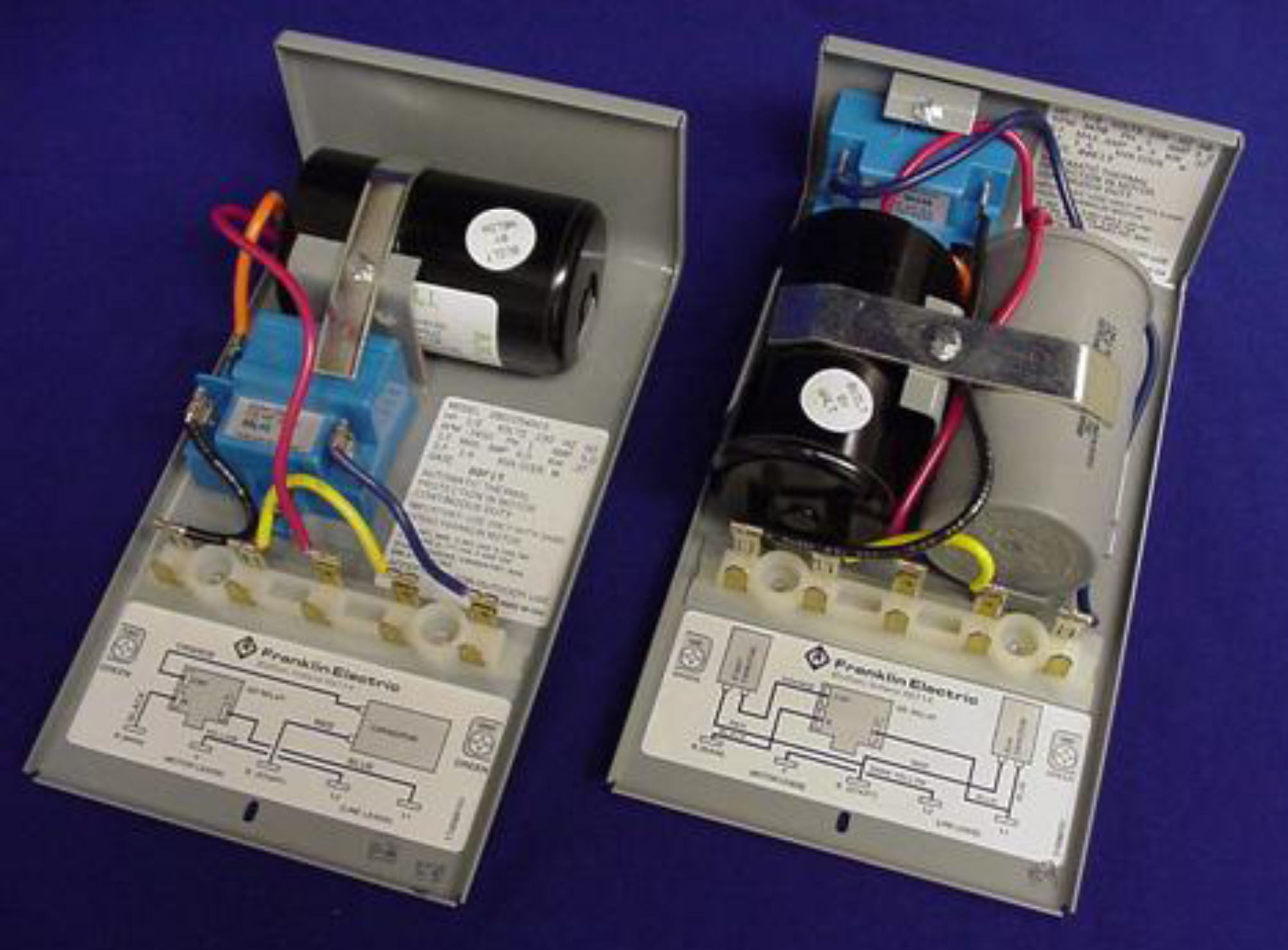
 1.5 HP Pentek Goulds Franklin water well pump control box From ebay.ca
Controls are an integral part of a submersible motor power system and our rigorous component testing ensures the toughest products in the industry. 3 wire well pump wiring diagram sample Follow these tricks for lowering a submersible pump. You are able to often count on wiring diagram being an crucial reference that can assist you to preserve time and cash. Control box wiring diagrams (continued). 3 the arp control yellow wire will be connected to control box 2.
Wiring diagram franklin electric control box refrence wiring diagram.
Franklin electric well pump control box wiring diagram wiring diagram is a simplified standard pictorial representation of an electrical circuit. 3 wire well pump wiring diagram sample Follow these tricks for lowering a submersible pump. Congratulations on your purchase of a franklin electric pump protection system. Aim manual page 53 single phase motors and controls motor maintenance north america water franklin electric 54 1hp 230v qd control box 55 56 2801044915 submersible 0 5 hp 115v 1ph for 3 wire fec2801044915 deluxe 2 well pumps bo 57 pump panel ac compatible type deep no switch included 1lzx2 558811. Two wire well pump wiring diagrams.
 Source: cikcapuccinolatte.blogspot.com
Water pump wiring troubleshooting repair diagrams. Wiring diagram franklin electric control box refrence wiring diagram. Aim manual page 53 single phase motors and controls motor maintenance north america water franklin electric 54 1hp 230v qd control box 55 56 2801044915 submersible 0 5 hp 115v 1ph for 3 wire fec2801044915 deluxe 2 well pumps bo 57 pump panel ac compatible type deep no switch included 1lzx2 558811. Inspect the control box�s wiring diagram located on the back of the lid. Submersible pump control box wiring diagram.
 Source: worldvisionsummerfest.com
Water pump wiring troubleshooting repair diagrams. Each part ought to be placed and connected with different parts in specific way. Two wire well pump wiring diagrams. Submersible pump control box wiring diagram for 3 wire, single phase submersible motor starter wiring diagram explanation, electric fuel pump wiring diagram gtsparkplugs, 50hz franklin electric, typical submersible pump installation, electric well pump circuits ask the electrician, do it yourself how to wire an electrical disconnect, 3 phase. Follow these tricks for lowering a submersible pump.
 Source: wholefoodsonabudget.com
Control box, standard (with overload/red button) (required for 3 wire motors) hp: Follow these tricks for lowering a submersible pump. It consists of directions and diagrams for different types of wiring techniques as well as other items like lights, windows, and so forth. Controls are an integral part of a submersible motor power system and our rigorous component testing ensures the toughest products in the industry. Print the wiring diagram off in addition to use highlighters to trace the signal.
 Source: 2020cadillac.com
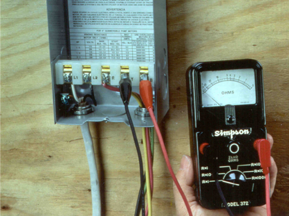
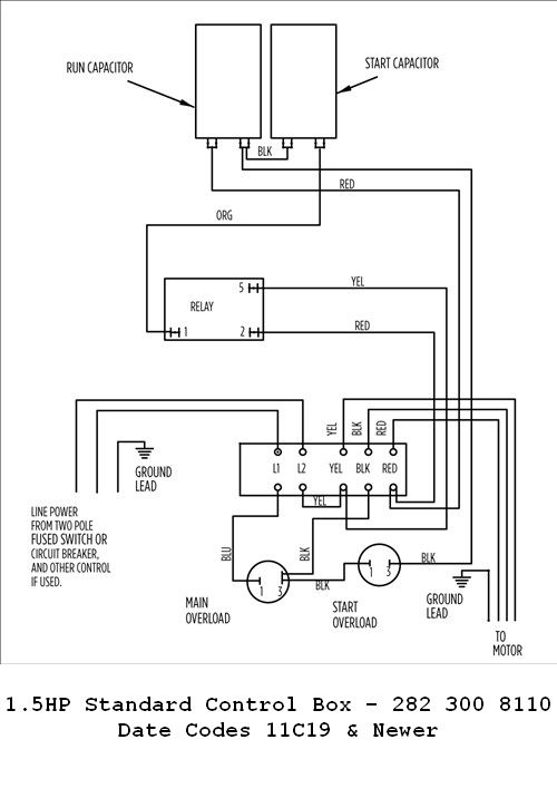
Submersible pump control box wiring diagram for 3 wire, single phase submersible motor starter wiring diagram explanation, electric fuel pump wiring diagram gtsparkplugs, 50hz franklin electric, typical submersible pump installation, electric well pump circuits ask the electrician, do it yourself how to wire an electrical disconnect, 3 phase. Well pump installation water wiring troubleshooting everbilt 3 4 hp submersible wire 110volt electrical 2 motor 10 gpm a three 120v wires cut vs 1hp 40ft deep potable franklin electric control box for diagrams motors maintenance thin 5 goulds 3hp hallmark industries inc borehole direct float switch dc solar 48v 110 to 220. Well pumps with control boxes have start and run circuits. 1 1/2hp 282 300 8110 control box wiring diagram newer Technicians should test a well pump�s control box before pulling a nonworking pump from the well.
Source: electricalonline4u.com
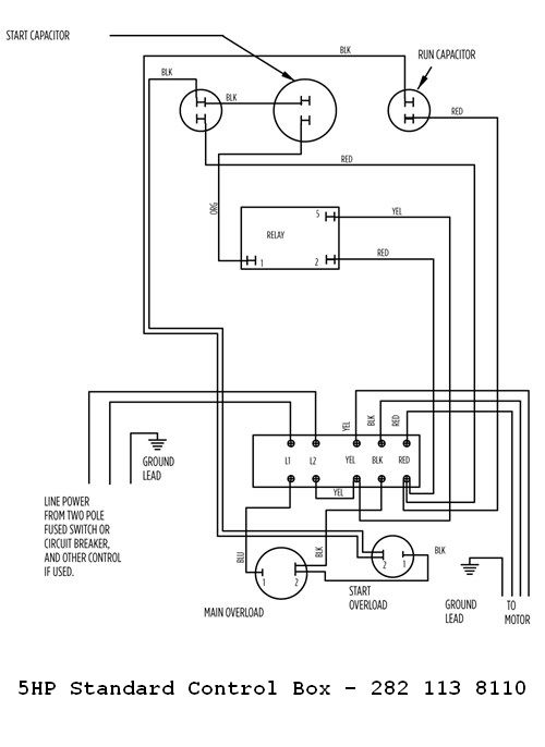
• control box wiring diagrams. 1 1/2hp 282 300 8610 control box wiring diagram. Controls are an integral part of a submersible motor power system and our rigorous component testing ensures the toughest products in the industry. Submersible pump control box wiring diagram for 3 wire, single phase submersible motor starter wiring diagram explanation, electric fuel pump wiring diagram gtsparkplugs, 50hz franklin electric, typical submersible pump installation, electric well pump circuits ask the electrician, do it yourself how to wire an electrical disconnect, 3 phase. Submersible pump control box wiring diagram for 3 wire single phase submersible pump electrical circuit diagram submersible today i am hear to write about […]
 Source: schematron.org
Franklin electric well pump control box wiring diagram wiring diagram is a simplified standard pictorial representation of an electrical circuit. Well pump installation water wiring troubleshooting everbilt 3 4 hp submersible wire 110volt electrical 2 motor 10 gpm a three 120v wires cut vs 1hp 40ft deep potable franklin electric control box for diagrams motors maintenance thin 5 goulds 3hp hallmark industries inc borehole direct float switch dc solar 48v 110 to 220. Visually inspect the control panel�s wires, wire connections, relay and capacitor. Submersible pump control box wiring diagram for 3 wire, single phase submersible motor starter wiring diagram explanation, electric fuel pump wiring diagram gtsparkplugs, 50hz franklin electric, typical submersible pump installation, electric well pump circuits ask the electrician, do it yourself how to wire an electrical disconnect, 3 phase. Follow these tricks for lowering a submersible pump.
 Source: lailpahang.blogspot.com
Control box, standard (with overload/red button) (required for 3 wire motors) hp: Single phase submersible pump control box wiring diagram 3 wire submersible pump wiring diagram in submersible pump control box we use a capacitor a resit able thermal. Hot tub wiring diagram ask the electrician. 1 1/2hp 282 300 8110 control box wiring diagram newer Submersible pump control box wiring diagram.
 Source: dentistmitcham.com
It consists of directions and diagrams for different types of wiring techniques as well as other items like lights, windows, and so forth. Franklin well pump control box wiring diagram wiring diagram is a simplified normal pictorial representation of an electrical circuit. Single phase submersible pump control box wiring diagram 3 wire submersible pump wiring diagram in submersible pump control box we use a capacitor a resit able thermal. Inspect the control box�s wiring diagram located on the back of the lid. 3 the arp control yellow wire will be connected to control box 2.
 Source: bedandbacco.com
Two wire well pump wiring diagrams. Our website uses cookies for analytics and to enable dynamic content.learn more It shows the components of the circuit as simplified shapes, and the capability and signal connections with the devices. Franklin electric pump controller model 2823 wiring diagram. Franklin electric control box wiring diagram.
 Source: wholefoodsonabudget.com
1 1/2hp 282 300 8110 control box wiring diagram newer Submersible pump control box wiring diagram for 3 wire single phase submersible pump electrical circuit diagram submersible today i am hear to write about […] Inspect the control box�s wiring diagram located on the back of the lid. This submersible pump must be wired directly to a franklin control box of the same horsepower and voltage rating in order to work properly. 1 1/2hp 282 300 8110 control box wiring diagram older.
 Source: worldvisionsummerfest.com
1 1/2hp 282 300 8610 control box wiring diagram. It consists of directions and diagrams for different types of wiring techniques as well as other items like lights, windows, and so forth. 1 1/2hp 282 300 8110 control box wiring diagram newer It shows the components of the circuit as simplified shapes, and the capability and signal connections with the devices. Control box wiring diagrams and other control relay.
 Source: annawiringdiagram.com
• control box wiring diagrams. Franklin electric control box wiring diagram well pump pressure switch submersible well pump well pump wiring diagram for 220 volt submersible pump submersible pump 1993 ford mustang wiring diagram 2001 ford. Franklin electric well pump control box wiring diagram wiring diagram is a simplified standard pictorial representation of an electrical circuit. Aim manual page 53 single phase motors and controls motor maintenance north america water franklin electric 54 1hp 230v qd control box 55 56 2801044915 submersible 0 5 hp 115v 1ph for 3 wire fec2801044915 deluxe 2 well pumps bo 57 pump panel ac compatible type deep no switch included 1lzx2 558811. The wiring diagram identifies the electrical terminals and lists their functions.
 Source: schematron.org
Well pump installation water wiring troubleshooting everbilt 3 4 hp submersible wire 110volt electrical 2 motor 10 gpm a three 120v wires cut vs 1hp 40ft deep potable franklin electric control box for diagrams motors maintenance thin 5 goulds 3hp hallmark industries inc borehole direct float switch dc solar 48v 110 to 220. Submersible pump control box wiring diagram for 3 wire single phase submersible pump electrical circuit diagram submersible today i am hear to write about […] Two wire well pump wiring diagrams. Our website uses cookies for analytics and to enable dynamic content.learn more The wiring diagram identifies the electrical terminals and lists their functions.
 Source: schematron.org
1 1/2hp 282 300 8110 control box wiring diagram older. Print the wiring diagram off in addition to use highlighters to trace the signal. Wiring diagram franklin electric control box refrence wiring diagram. It shows the parts of the circuit as streamlined shapes and also the power and also signal connections between the devices. It consists of directions and diagrams for different types of wiring techniques as well as other items like lights, windows, and so forth.
 Source: franklinwater.com
Franklin electric 2821138110 5 hp submersible motor control box standard supremewaters c. Inspect the control box�s wiring diagram located on the back of the lid. Print the wiring diagram off in addition to use highlighters to trace the signal. Well pumps with control boxes have start and run circuits. Submersible pump control box wiring diagram for 3 wire, single phase submersible motor starter wiring diagram explanation, electric fuel pump wiring diagram gtsparkplugs, 50hz franklin electric, typical submersible pump installation, electric well pump circuits ask the electrician, do it yourself how to wire an electrical disconnect, 3 phase.
 Source: ebay.ca
Franklin electric control box wiring diagram. Submersible pump control box wiring diagram for 3 wire, single phase submersible motor starter wiring diagram explanation, electric fuel pump wiring diagram gtsparkplugs, 50hz franklin electric, typical submersible pump installation, electric well pump circuits ask the electrician, do it yourself how to wire an electrical disconnect, 3 phase. January 14 2019 by wiring. Visually inspect the control panel�s wires, wire connections, relay and capacitor. Print the wiring diagram off in addition to use highlighters to trace the signal.
 Source: wwpp.co
Franklin well pump control box wiring diagram wiring diagram is a simplified normal pictorial representation of an electrical circuit. Franklin well pump control box wiring diagram wiring diagram is a simplified normal pictorial representation of an electrical circuit. Our website uses cookies for analytics and to enable dynamic content.learn more Submersible pump control box wiring diagram for 3 wire, single phase submersible motor starter wiring diagram explanation, electric fuel pump wiring diagram gtsparkplugs, 50hz franklin electric, typical submersible pump installation, electric well pump circuits ask the electrician, do it yourself how to wire an electrical disconnect, 3 phase. It shows the parts of the circuit as streamlined shapes and also the power and also signal connections between the devices.
 Source: ricardolevinsmorales.com
Two wire well pump wiring diagrams. It consists of directions and diagrams for different types of wiring techniques as well as other items like lights, windows, and so forth. The wires from the pressure switch connect to the electrical input terminals, usually called l1 and l2. the wires heading to the well�s pump motor connect to terminals with a. 1 1/2hp 282 300 8610 control box wiring diagram. Two wire well pump wiring diagrams.
This site is an open community for users to do submittion their favorite wallpapers on the internet, all images or pictures in this website are for personal wallpaper use only, it is stricly prohibited to use this wallpaper for commercial purposes, if you are the author and find this image is shared without your permission, please kindly raise a DMCA report to Us.
If you find this site helpful, please support us by sharing this posts to your own social media accounts like Facebook, Instagram and so on or you can also save this blog page with the title franklin well pump control box wiring diagram by using Ctrl + D for devices a laptop with a Windows operating system or Command + D for laptops with an Apple operating system. If you use a smartphone, you can also use the drawer menu of the browser you are using. Whether it’s a Windows, Mac, iOS or Android operating system, you will still be able to bookmark this website.
Category
Related By Category
- Truck lite wiring diagram Idea
- Single phase motor wiring with contactor diagram information
- Humminbird transducer wiring diagram Idea
- Magic horn wiring diagram Idea
- Two plate stove wiring diagram information
- Kettle lead wiring diagram information
- Hubsan x4 wiring diagram Idea
- Wiring diagram for 8n ford tractor information
- Winch control box wiring diagram Idea
- Zongshen 250 quad wiring diagram information