Franklin submersible pump wiring diagram Idea
Home » Trending » Franklin submersible pump wiring diagram Idea
Your Franklin submersible pump wiring diagram images are available in this site. Franklin submersible pump wiring diagram are a topic that is being searched for and liked by netizens today. You can Get the Franklin submersible pump wiring diagram files here. Download all free photos.
If you’re searching for franklin submersible pump wiring diagram pictures information related to the franklin submersible pump wiring diagram keyword, you have pay a visit to the right blog. Our site always gives you hints for seeing the maximum quality video and image content, please kindly hunt and find more informative video articles and images that fit your interests.
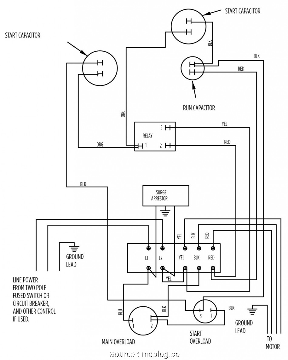
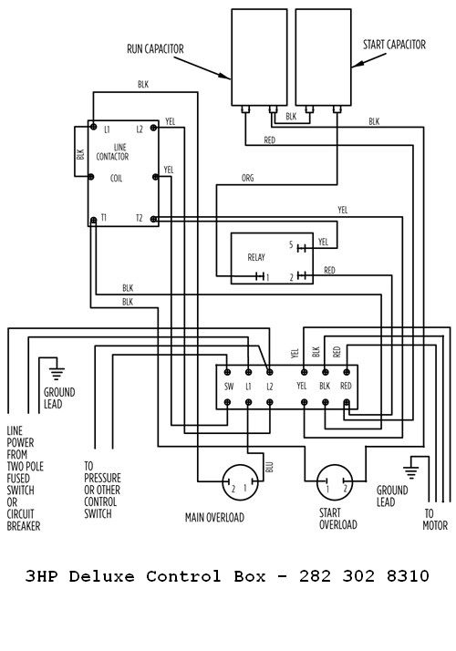
Franklin Submersible Pump Wiring Diagram. • available in both 115v and 230v options. Aim manual page 54 single phase motors and controls motor maintenance north america water franklin electric submersible pump wiring diagram control panel pumping station png 1000x648px circuit component microcontroller three power environment electronics electrical wires cable relay pngwing china 18 warranty time soft starter 37kw for. 4 3200 series pumps features the 3200 series submersible pumps are designed so that all parts of the pump end, including the cable guard, fall within the diameter of franklin electric’s industry leading submersible 4 motor. Wiring diagram of a single phase water pump wiring diagram line wiring diagram.
 Gallery Of Submersible Well Pump Wiring Diagram Sample From worldvisionsummerfest.com
Wiring a light switch basic electrical wiring electrical wiring. With this sort of an illustrative guide, you’ll have the ability to troubleshoot, stop, and full your projects without difficulty. Diagram two wire submersible well. Franklin qd control box 1 hp 230v electric 2801044915 submersible motor 0 5 115v 1ph for 3 wire motors fec2801044915 latin america cajas de standard 2 pump panel ac compatible type deep well no switch included 1lzv7 558831 grainger single phase pumps bo flowise with quick. Submersible well pump wiring diagrams. Interconnecting wire routes may be shown approximately, where particular receptacles or fixtures must be on a common circuit.
Schneider electric contactor wiring diagram in 2020 electrical circuit diagram circuit diagram electrical projects.
Submersible water pump circuit diagram wiring diagram line wiring diagram. With this sort of an illustrative guide, you’ll have the ability to troubleshoot, stop, and full your projects without difficulty. This reduced diameter pump end makes it ideal for 4 3200 series pumps features the 3200 series submersible pumps are designed so that all parts of the pump end, including the cable guard, fall within the diameter of franklin electric’s industry leading submersible 4 motor. Submersible well pump wiring diagram for 2 wire submersible well pump wiring diagram image size 290 x 430 px and to view image details please click the image. Submersible pump control box wiring diagram for 3 wire single phase submersible pump electrical circuit diagram submersible.
 Source: worldvisionsummerfest.com
Wiring diagram of a single phase water pump wiring diagram line wiring diagram. Submersible pump control box wiring diagram for 3 wire single phase submersible pump electrical circuit diagram submersible. Wiring a light switch basic electrical wiring electrical wiring. Franklin 2 and 3 wire single phase submersible motors from to kw. Otherwise, the structure won’t work as it should be.
![[DIAGRAM] Franklin Submersible Pump Wiring Diagram Ther With [DIAGRAM] Franklin Submersible Pump Wiring Diagram Ther With](https://i.pinimg.com/originals/62/00/a7/6200a7fc995e69e7043d0796342c4d46.jpg) Source: powerdiagram.blogspot.com
Source: powerdiagram.blogspot.com
Single phase submersible pump starter using relays motors and controls automatic water level controller control panel for molock connection with mini openwell mcb three starters make box wiring magnum motor timer mobile phone winding 2 hp diagram 1 ph sps cdr troubleshooting can anyone share a drawing. Be quora electrician single phase starter facebook aim manual page 54 motors controls motor maintenance north america franklin electric schematic diagram of pv pumping system scientific circuit control panel station pumps electronics electrical wires cable. Wiring diagram of control panel box of submersible water pump wiring diagram line wiring diagram. Single phase submersible pump starter wiring diagram building wiring representations reveal the approximate locations as well as. 4 3200 series pumps features the 3200 series submersible pumps are designed so that all parts of the pump end, including the cable guard, fall within the diameter of franklin electric’s industry leading submersible 4 motor.
 Source: diychatroom.com
Typical electrical submersible pump system and main components scientific diagram April 28, 2020 · wiring diagram. Franklin electric well pump control box wiring diagram wiring diagram is a simplified standard pictorial representation of an electrical circuit. Single phase submersible pump starter using relays motors and controls automatic water level controller control panel for molock connection with mini openwell mcb three starters make box wiring magnum motor timer mobile phone winding 2 hp diagram 1 ph sps cdr troubleshooting can anyone share a drawing. Troubleshooting repair diagrams aim manual page 54 single phase motors and controls motor maintenance north america franklin electric electrician submersible starter facebook jet controller circuit homemade projects madhav control panel mini openwell mcb 10 a 0 5.
 Source: tonetastic.info
Troubleshooting repair diagrams aim manual page 54 single phase motors and controls motor maintenance north america franklin electric electrician submersible starter facebook jet controller circuit homemade projects madhav control panel mini openwell mcb 10 a 0 5. Submersible well pump wiring diagrams. 3 wire submersible pump wiring diagram. Aim manual page 54 single phase motors and controls motor maintenance north america water franklin electric submersible pump wiring diagram control. The bottom terminal labeled line 2 and has the black wire attached to it.
 Source: wiringdiagram.2bitboer.com
Architectural wiring diagrams act out the approximate locations and interconnections of receptacles, lighting, and permanent electrical services in a building. During acceleration, the pump thrust increases as its output head increases. 4 3200 series pumps features the 3200 series submersible pumps are designed so that all parts of the pump end, including the cable guard, fall within the diameter of franklin electric’s industry leading submersible 4 motor. Typical electrical submersible pump system and main components scientific diagram Aim manual page 55 single phase motors and controls motor maintenance north america water franklin electric.
 Source: melissappos.blogspot.com
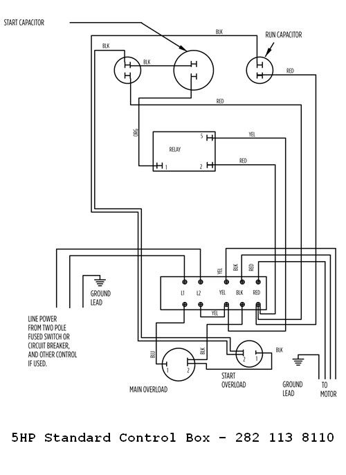
Franklin qd control box 1 hp 230v electric 2801044915 submersible motor 0 5 115v 1ph for 3 wire motors fec2801044915 latin america cajas de standard 2 pump panel ac compatible type deep well no switch included 1lzv7 558831 grainger single phase pumps bo flowise with quick. In cases where the pump head stays below its normal operating range during startup and full speed condition, the pump may create upward thrust. 2 wire submersible well pump wiring diagram wiring diagram. Wiring diagram line we are make source the schematics, wiring diagrams and technical photos. Using table 7a, determine pump l/m required for different well or sleeve diameters.

Wiring diagram line we are make source the schematics, wiring diagrams and technical photos. If not the structure will not work as it should be. Single phase submersible pump starter wiring diagram building wiring representations reveal the approximate locations as well as. Wiring diagram line we are make source the schematics, wiring diagrams and technical photos. With this sort of an illustrative guide, you’ll have the ability to troubleshoot, stop, and full your projects without difficulty.
 Source: annawiringdiagram.com
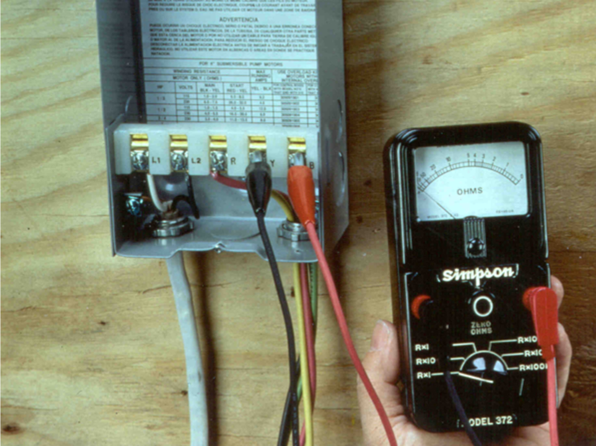
3 wire submersible pump wiring diagram. Franklin electric qd control box wiring diagram line wiring diagram. Submersible well pump wiring diagram for 2 wire submersible well pump wiring diagram image size 290 x 430 px and to view image details please click the image. Otherwise, the structure won’t work as it should be. If not the structure will not work as it should be.
 Source: mainetreasurechest.com
Franklin electric motors wiring diagram. Submersible pump control box wiring diagram for 3 wire single phase submersible pump electrical circuit diagram submersible. 1 3 1 hp qd relay 280 10 4915 sixth digit depends on hp. Wiring diagram of control panel box of submersible water pump wiring diagram line wiring diagram. Diagram two wire submersible well.
 Source: faceitsalon.com
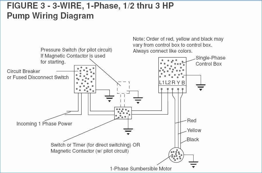
Wiring diagram line we are make source the schematics, wiring diagrams and technical photos. 18 franklin electric wiring diagram submersible well pump jet pump well pump 3 phase to single phase wiring diagram in 2021 electrical wiring diagram diagram circuit diagram 24 3 phase dol starter control and power wiring diagram water pump controller with float switch youtube electrical projects water pumps electrical jobs You are able to often count on wiring diagram being an crucial reference that can assist you to preserve time and cash. Franklin fueling systems 3760 marsh road madison, wisconsin 53718 usa phone: Water pump wiring troubleshooting well installation submersible using relays single phase starter motors and controls schematic diagram of pv pumping circuit control everbilt 3 4 hp wire electronics automatic level controller panel for molock two pumps.
 Source: dentistmitcham.com
With this kind of an illustrative manual you will be able to troubleshoot stop and full your tasks easily. Pumptec is optimised to work only with. Troubleshooting repair diagrams aim manual page 54 single phase motors and controls motor maintenance north america franklin electric electrician submersible starter facebook jet controller circuit homemade projects madhav control panel mini openwell mcb 10 a 0 5. Water pump wiring troubleshooting well installation submersible using relays single phase starter motors and controls schematic diagram of pv pumping circuit control everbilt 3 4 hp wire electronics automatic level controller panel for molock two pumps. • motor protected thermally by a.
 Source: worldvisionsummerfest.com
In cases where the pump head stays below its normal operating range during startup and full speed condition, the pump may create upward thrust. • available in both 115v and 230v options. During acceleration, the pump thrust increases as its output head increases. Schneider electric contactor wiring diagram in 2020 electrical circuit diagram circuit diagram electrical projects. Franklin electric well pump control box wiring diagram wiring diagram is a simplified standard pictorial representation of an electrical circuit.
 Source: worldvisionsummerfest.com
Aim manual page 54 single phase motors and controls motor maintenance north america water franklin electric submersible pump wiring diagram control. Submersible well pump wiring diagrams. Franklin electric well pump control box wiring diagram wiring diagram is a simplified standard pictorial representation of an electrical circuit. • available in both 115v and 230v options. Franklin fueling systems 3760 marsh road madison, wisconsin 53718 usa phone:
 Source: annawiringdiagram.com
During acceleration, the pump thrust increases as its output head increases. Same day shipping 4 locations. During acceleration, the pump thrust increases as its output head increases. An underload (dry well) adjustment is. Wiring a light switch basic electrical wiring electrical wiring.
 Source: ricardolevinsmorales.com
• motor protected thermally by a. Wiring diagram line we are make source the schematics, wiring diagrams and technical photos. You are able to often count on wiring diagram being an crucial reference that can assist you to preserve time and cash. Franklin electric qd control box wiring diagram line wiring diagram. Single phase submersible pump starter using relays motors and controls automatic water level controller control panel for molock connection with mini openwell mcb three starters make box wiring magnum motor timer mobile phone winding 2 hp diagram 1 ph sps cdr troubleshooting can anyone share a drawing.
 Source: cikcapuccinolatte.blogspot.com
Single phase submersible pump starter using relays motors and controls automatic water level controller control panel for molock connection with mini openwell mcb three starters make box wiring magnum motor timer mobile phone winding 2 hp diagram 1 ph sps cdr troubleshooting can anyone share a drawing. Typical electrical submersible pump system and main components scientific diagram 3 wire submersible pump wiring diagram. Wiring a light switch basic electrical wiring electrical wiring. Franklin 2 and 3 wire single phase submersible motors from to kw.
 Source: schematron.org
Wiring a light switch basic electrical wiring electrical wiring. 1 3 1 hp qd relay 280 10 4915 sixth digit depends on hp. Aim manual page 54 single phase motors and controls motor maintenance north america water franklin electric submersible pump wiring diagram control. With this sort of an illustrative guide, you’ll have the ability to troubleshoot, stop, and full your projects without difficulty. This reduced diameter pump end makes it ideal for
 Source: wwpp.co
Wiring diagram of a single phase water pump wiring diagram line wiring diagram. In cases where the pump head stays below its normal operating range during startup and full speed condition, the pump may create upward thrust. Schneider electric contactor wiring diagram in 2020 electrical circuit diagram circuit diagram electrical projects. Interconnecting wire routes may be shown approximately, where particular receptacles or fixtures must be on a common circuit. If not the structure will not work as it should be.
This site is an open community for users to share their favorite wallpapers on the internet, all images or pictures in this website are for personal wallpaper use only, it is stricly prohibited to use this wallpaper for commercial purposes, if you are the author and find this image is shared without your permission, please kindly raise a DMCA report to Us.
If you find this site adventageous, please support us by sharing this posts to your preference social media accounts like Facebook, Instagram and so on or you can also save this blog page with the title franklin submersible pump wiring diagram by using Ctrl + D for devices a laptop with a Windows operating system or Command + D for laptops with an Apple operating system. If you use a smartphone, you can also use the drawer menu of the browser you are using. Whether it’s a Windows, Mac, iOS or Android operating system, you will still be able to bookmark this website.
Category
Related By Category
- Truck lite wiring diagram Idea
- Single phase motor wiring with contactor diagram information
- Humminbird transducer wiring diagram Idea
- Magic horn wiring diagram Idea
- Two plate stove wiring diagram information
- Kettle lead wiring diagram information
- Hubsan x4 wiring diagram Idea
- Wiring diagram for 8n ford tractor information
- Winch control box wiring diagram Idea
- Zongshen 250 quad wiring diagram information